
ACCORDION REPAIR MADE SIMPLE 2
© 2014 George Bachich All rights recerved.Use these links to jump directly to the named articles:
RENEWING TREBLE VALVES
SETTING UP A TREBLE KEYBOARD FOR A SHALLOW ACTION
ADJUSTING KEY TENSION
WAXING WITH A MODIFIED SOLDERING IRON
WAXING WITH A WAX POT AND SPOON
MAKING AN OVERSIZE AIR RELEASE VALVE
INSTALLING RHINESTONES ON BASS BUTTONS
REPLACING BELLOWS TAPE
REPLACING BASS BUTTONS
DISASSEMBLING A BASS MACHINE
INSTALLING A NEW BELLOWS
RE-VALVING THE BASS SIDE AND SETTING UP THE BASS MACHINE
REMOVABLE BASS MACHINES
SORTING OUT MIXED UP BASS PIPES
SORTING OUT MIXED UP BASS BUTTONS
Questions? Comments? Contact me via email.
Renewing, refacing, re-valving; whatever you choose to call it, replacing the felt/leather facing on your treble valves will make your accordion use less air and will reduce the clattering of the keyboard. Old hard felt is less effective as a cushion, and compressed felt allows the key to travel farther and faster before closing. Both factors contribute to a noisy, clunky keyboard. Re-valving and re-leveling will go a long way toward making your keyboard look, feel, and work like new.
Begin by removing the treble grille and treble switch assembly, and disassembling the keyboard. Unless your accordion has a tone chamber, you can technically re-valve without disassembling the keyboard, but by taking all the keys out you will be less likely to drop brittle wax debris into your treble register slides or into the reed blocks when you twist off the pallets. This is also your best chance to clean under the treble keys and to clean the spindles, as well as to install new felt stops under the keys, and/or adjust the depth of the keyboard action. See the article on setting up a treble keyboard for specific instructions.
Next, measure the thickness of the felt and leather laminate on your treble pallets. Some accordions have different thicknesses on the white and black keys. If your accordion has a tone chamber, the valves in the chamber may have a different thickness facing from those outside the chamber. Technically, you can change these thicknesses, but doing so will significantly increase the amount of bending you will have to do on the key rods. This is particularly troublesome on keys in the black key row, which often have very short rods. If your accordion has just leather facing with no felt cushion behind it, you may choose to add some padding, but the easiest way is to match the original thicknesses.
Once you have all the keys out, note how the pallets are fastened to the key rods. Your pallets will most likely be fastened to the rods with reed wax, which will break away fairly easily as you twist the pallet off the rod. However, some pallets have small plastic sleeves that slip over the ends of the key rods, which in most cases slip off and back on fairly easily. A few accordions have the pallets glued to the key rods, in which case this next step may not apply, which is to remove the pallets from the key rods. If they are fastened on with wax, you may be tempted to leave them on to save the work of re-waxing them, but you will probably dislodge some of them during the cleaning process anyway, and once off the rods the pallets are easier to handle, so you might as well take them off right at the beginning. The black key pallets are sometimes a different height, length, and/or width than the white key pallets. If so, keep them separate.
Strip the old valve facings off your pallets and scrape off the old glue. Applying heat may help soften the glue, so you might try using the modified soldering iron described in the article on installing a new bellows.
Check to make sure pallets are not arched. Place them flat side down on a flat table and try to push a .003" metal feeler gage under the center and ends. If you find .003" or more clearance under any part of a pallet, sand it flat. If it is too thin to sand flat, then either replace it or glue on another thin layer and sand that flat. Finish by sanding lightly to cross hatch the surface for better glue adhesion. You want a nice flat, clean surface to apply the new facing.
Select the valve facing material of appropriate thickness for each class of pallet. The traditional Italian valve facing material from FRM Enterprises comes in sheets large enough to do a whole accordion for about $18. You will have to cut the sheet into strips of the proper width to fit your pallets. I use a wheel cutter (available in fabric stores for about $20), a metal ruler/straightedge, and the pallet itself to gauge the width of the strip. Once you have it cut into strips, use the wheel cutter and straight edge to cut off lengths to fit your pallets.
Your pallets are most likely to be wood, but may also be plastic or metal. If you have metal pallets you may choose to use a thin coat of hot glue or fabric glue for better adhesion, but if you have wood or plastic, use Elmer's white glue. Lay your newly cut valve facings on your work table felt side up. With a small brush, paint an even, thin coat of glue onto the bottom of a pallet. You want thorough coverage, but you don't want to leave any excess glue that might soak into the felt and harden it. Be sure to get the right pallet matched to the right thickness valve facing, then center it carefully over one of your valve facings, press the glued pallet onto the felt, and leave it to dry. Repeat for each pallet.
Before proceeding any further, be sure you fully understand the article on setting up a treble keyboard, including its specific instructions on how to set the depth of action and level the keyboard. This is your chance to get your keyboard set up exactly the way you want it.
Once you have decided on the proper height for your black keys, install all the black keys (sans pallets) back into the keyboard (if your black and white keys are all on one spindle, you may be tempted to install the white keys also, but you will have an easier time if you don't). Place all the black key pallets into position, carefully centering them over their ports and lining all their front edges up against a straight edge, making sure they won't interfere with operation of the white key pallets. Use your keyboard leveling/bending tools to bend each key rod as required to center it in the groove in the top of its pallet and to cause the rod end to lie level and flat in that groove at the same time that the top of the black key is at the proper height and exactly level with all the others.
When you have all the key rods properly adjusted, wax them into the pallets. For details, see the article on waxing with a modified soldering iron. Take special care not to let any molten wax run down the sides of the pallet far enough to foul the felt padding or leather valve facing. If this happens, you will have to replace that leather/felt valve facing (don't panic; it is easy to replace).
Even though all pallets were lying flat on their ports when you waxed them in, shrinkage of the wax as it cools might lift one end of the pallet, so check all corners of each valve with a feeler gauge made from a thin piece of paper. Use your bending tools to rotate the pallet as necessary for a perfect seal all around, and to tweak the rod as necessary to center the pallet over its ports, and to get your black keys exactly level.
Repeat these same procedures for the white keys, then check for any valves that leak under bellows pressure. Use your paper feeler gauge and your bending tools to diagnose and cure any such leaks, and for a final leveling of the keyboard. When all is well, reinstall the treble switch assembly and treble grille, and play yourself a congratulatory song.
To return to the table of contents for this page, click here.
One of the nicest things you can do for yourself if you don't already have it, is to set up your keyboard for nice shallow action. Especially of you play fast or use glissandos in your music, you and those around you will appreciate what a nice shallow action does for your playing. By shallow, I mean somewhere between 3/16 and 1/8 inch, measured right at the end of the white keys. This is clearly a matter of personal preference, but I find anything over 3/16 inch a bit cumbersome, and anything less than 1/8 inch does not provide enough tactile feedback. Besides, some of the valves on your accordion may not open far enough to allow the bassoon reed to sound if you set the action too shallow.
By the way, all the following is based on the assumption that your accordion does not have a tone chamber. If it does, the same basic considerations apply, but the job is much more complicated, difficult, and time consuming because each treble key has two valves mounted to it. One of the valves is in the normal position and easy to adjust, but the other is in the tone chamber, where it is difficult to reach and to see, and therefore much more difficult to adjust properly. The challenge is that both valves have to close simultaneously and seal perfectly at the same instant that the key arrives at the correct level with all the other keys. With some experience and the right tools this challenge is manageable, but the first keyboard you set up should probably not be on an accordion with a tone chamber. Since this article is directed primarily toward those who have not previously set up a keyboard, it is tailored to non- tone chamber accordions.
To find the minimum practical white key travel for your accordion, remove the treble grille and identify all the white keys (if any) that have short key rods with their valves located in the black key row, nearest the keyboard. If you have a normal full size 41/120 accordion with 19" keyboard, you probably will not find any. But if you have a ladies' size or intermediate size, or if you have an extended keyboard with more than 41 notes, you will very likely find that from 1 to 3 of your white keys have stubby little key rods. They are usually C keys or E keys. The problem is that due to their shorter lever arm these valves do not open as far as the other white key valves for the same amount of key deflection, and if you make the action too shallow, they may not open far enough to allow enough air to flow through the reeds behind them to properly sound the bassoon reed, which requires more air than the others. This is particularly troublesome if the bassoon reeds are located at the rearmost ports because the rear of the pallet, being closer to the fulcrum, does not lift as far off the ports.
Some accordion designers eliminate this problem by using compound levers on some or all of these keys. They attach the valve to a long lever hinged at the forward side of the foundation plate. This lever is lifted near its center by the stubby key rod, thus doubling the lift on the valve. If your accordion has no white key valves in the black key row, or if it has compound levers on those notes, you can relax, because the lower practical limit of white key travel is lower than you would want it in any case. But if you find one or more without compound levers, choose the lowest of those notes to test.
With the Master switch on, and with light bellows pressure, play that note normally and measure the depth of the key deflection required to make all the reeds on that note respond satisfactorily. This is the minimum practical key travel for this key, and unless you want to make the stop under this key lower than all the other key stops (not recommended), it is the minimum practical travel for all of your white keys.
Next, decide how shallow you want your key action to be. As long as that measurement is greater than your practical minimum, you have no worries. If it is less than your practical minimum, you will either have to compromise or redesign your accordion to have compound levers. Whichever course you choose, the white key travel you select is the basis for the rest of your work on this project.
There are two ways to limit the key travel to your chosen value. You can limit how far up the keys can travel, and you can limit how far down they can travel. You will probably do a little of both.
Upward travel is adjusted by bending the key rod. When the valve is closed, the key is just so high, and cannot go higher without bending the rod. (see the article on bending key rods and making bending tools). You will bend the key rods to set the key height exactly where you want it, usually flush with the ends of the keyboard cabinet. This usually looks the best, and is also very convenient, because you can simply place a long straightedge across all the keys, resting directly on top of the cabinet at each end and bend the key rods until all the keys just barely touch the straightedge and are not deflected by the straightedge when you press the straightedge down onto the ends of the cabinet. Any resulting movement is very easy to see, so this method allows very precise keyboard leveling.
Make your initial bends as close as possible to the keys, and as far as possible from the pallets. If significant bending is required, you will find that one end or the other of the pallet has lifted off the foundation plate, which, if uncorrected, will cause the valve to leak. Make your second bend to correct this as close to the pallet as possible. Naturally, this second bend will impact the level of your key, so you will have to make another bend as close to the key as possible to correct that. You may go back and forth several times before you finally get it right. The point to remember is that bends made to raise or lower the key should be made close to the key, and bends to rock the pallet into parallel with the foundation plate should be made close to the pallet. Check all corners of each pallet with a feeler gauge cut from thin paper. For a perfect seal, you want to feel equal drag on the paper as you pull it out from under each corner.
Once you have leveled your keyboard (set the upward limit of white key travel and got every valve sealing perfectly), the next step is to take out all the treble keys (see the article on disassembling the treble keyboard). Also remove the long felt strip (key cushion/key stop), which you will find glued to the cabinet under the ends of the white key bodies, and the short felt or leather key cushions/stops glued to the cabinet at the end of each black key slot. Scrape off any old glue and felt residue.
As you have surmised by now, the downward travel is limited by felt stops (cushions) placed under the keys (green in the photo below). The stops are under the key body, not under the keytop overhangs at the ends of the white keys. Putting stops under the white keytop overhangs is a sure fire recipe for broken or delaminated keytops.

If you have a wooden keyboard like the one above, you will notice that the keyboard cabinet slots for the black keys are shorter than the slots for the white keys. Assuming you made sure your keys were numbered as you took them out, by counting short slots and long slots up from the bottom of the keyboard you can easily determine which keys go where. If your keyboard is aluminum, the slots may all look the same, in which case you will have to count more carefully, especially if your white and black keys have separate numbering systems.
Install a white key and an immediately adjacent black key in their proper positions near the center of the keyboard. You are choosing the approximate middle in order to be able to see and measure under the keys, and to be able to test various thicknesses of key stop material without taking the keys out each time. You are placing a black key immediately adjacent to a white key to allow setting the black key upward travel limit at the point where the top of the black key is exactly parallel to the top of the white key when they are both at their upward travel limits.
When you have properly adjusted that black key's upward limit, measure the difference in height between the white and black keys at rest against their upward stops (i.e., with both of their valves closed). Fabricate two wooden shims exactly this height by about 1/2 inch wide and 2 inches long. You will eventually tape these shims onto the cabinet ends in line with the ends of the black keys, so the straightedge can be rested on these shims while you level the black keys.
The next steps are to select the right combination of materials to use as white key stops to limit their downward travel to exactly the distance you selected early on, and to select the correct materials to use as black key stops to prevent the black keys from submerging below the level of the white keys when the white keys are at rest at their upward limit (you don't want excessive black key travel to cause you to inadvertently depress a white key while playing). The single white key and black key you have installed are your test beds for selecting the right material thicknesses.
If the clearance under your single white key (measured at the future key stop location) is not more than 1/8 inch in excess of your chosen key travel dimension, you can use felt of the correct thickness to stop your key where you want it to stop. However, it may not be wise to use felt thicker than 1/8 inch, because it will compress too much, giving the keyboard a mushy feel. In case the clearance under your white key is more than 1/8 inch in excess of your chosen key travel distance, you will need to fabricate a long wooden shim of the correct thickness and width to be glued and clamped in place under the 1/8" felt white key stop.
Select your black key stop material in the same way, and cut individual pieces to glue into place, using one of the old stops as a pattern. These are in a much more difficult place to clamp, so if your shims (if any) are not too thick, consider making them of scrap leather and gluing them to the wood with fabric glue, which sets much more quickly. If you make your new black key stops wider or longer than the originals, take care that they will not interfere with the operation of the black keys or the adjacent white keys. Try your various shims and cushion (key stop) materials under your test keys before gluing anything in place.
Once you are happy with your selection, remove your test keys and glue and clamp the long wooden shim in place (if you are using one) using Elmer's wood glue or equal, and glue your black key shims (if any) in place with the glue of your choice. When the glue has dried, glue your chosen felt key cushions/stops on top of the shims, using a very light coat of Elmer's, wood glue so as not to allow excess glue to soak into the felt and harden it. If you are also changing the felt trim under the white key overhangs, now is the time to do it.
Now you are ready. Install the black keys first and use your bending tools to level them (with the wooden shims taped in place under the ends of the straightedge, naturally). As with the white keys, bends made to raise or lower the key should be made close to the key, and bends to rock the pallet into parallel with the foundation plate should be made close to the pallet. This is particularly challenging on black keys with short key rods, but avoid the temptation to hold the key and bend the rod. If you have an old style wooden key with the key rod driven into it like a nail, this could tear the rod out of the key, or loosen it, which opens an entirely new can of worms. If you have aluminum key rods that extend all the way through the key, you may overstress the key hinge. Stick to the standard procedure, which is to grip the rod with two bending tools, one on either side of the point where you want it to bend.
If this standard procedure is clearly not working, then the nuclear solution is to twist the pallet off the key rod, clean all the old wax out of the pallet and revalve it, as the old valve facing is likely to have a waffle pattern impressed into it by the ports under it, and you will probably not be able to get it precisely back into position to seal properly (see the article on renewing treble valves). With the pallet off, use pliers on the end of the key rod to bend it into the proper position to lie flat in the slot on top of the re-valved pallet when the key is level. When you have it right, center the pallet over its ports, align it with neighboring pallets, and wax the key rod back into the pallet.

Once you have your black keys level and sealing perfectly, reinstall the white keys, which were previously leveled. Play the accordion to check for leaks. If any leaks are felt or heard, first try high inward bellows pressure with the Master switch on to see if enough air is leaking to sound a reed, in which case you can identify the note by ear. Be aware that you will be hearing the piccolo reed, so the leak may be an octave or two farther down the keyboard (pitch-wise) than you initially think. With the grille still off, you should be able to identify the leaking pallet by pressing down on it to see if that temporarily stops the leak. When you have identified it, adjust it to seal properly using the procedures above.
If you cannot readily identify the leaking note by pitch, set the accordion on its feet and use the bellows leak down procedure described in the article on finding leaks. When you finally have eliminated all leaks, put the grille back on and use your nice shallow keyboard action to play your favorite song.
To return to the table of contents for this page, click here.
WAXING WITH A MODIFIED SOLDERING IRON
When you need to wax but the job is too small to justify firing up your wax pot, use a modified 15 watt soldering iron. Bigger irons produce too much heat and will cause your wax to smoke, driving off volatile compounds and causing premature aging and embrittlement of the wax. Even a 15 watt iron produces too much heat unless you modify the tip to dissipate it.
Make a heat sink/waxing tip from a piece of copper flashing and rivet it to your soldering tip. Longer soldering tips are better because they allow more secure mounting of the heat sink. The heat sink should be approximately 3/4 inch wide by 1 1/4 inch long.
Remove the insulation from a short piece of solid (not stranded) copper electrical wire and cut it into two short lengths to use as rivets. Before removing the soldering tip from the iron, file one side of the last 3/4 inch of it flat to provide more bearing surface for the heat sink. Then drill two holes in it the same diameter as the wire, with the holes centered on the flat surface and 1/2 inch apart.
Hold the copper heat sink firmly against the flat side of the soldering tip and use the holes in the soldering tip as a template to drill matching holes along the longest centerline of the heat sink. Clean off all burrs, then place the heat sink back on the flat side of the soldering tip, align the holes, and install the rivets.
Trim the rivets so they protrude about one wire diameter beyond the assembled waxing tip on each side. Hold the heat sink and soldering tip firmly together while you set the rivets with a few light taps of a hammer on an anvil. The rivets should flare to about 1.5 times their original diameter. Reinstall the finished tip into the soldering iron, and you are ready to go.

For this kind of waxing you need to have your wax formed into rods about the diameter of a pencil so you can melt the wax against the waxing tip and feed it into the work as it melts. Line a wide, shallow flat bottomed container with waxed paper. Pour hot wax into the container to a depth of about 1/4 inch. After it cools, cut it into strips about 1/4 inch wide and peel them off the waxed paper. Alternatively, you can set your block of reed wax in the sun to warm it to near body temperature, then cut off pieces to roll between your palms until they are the size and shape you want.
You can use this waxing iron to deliver molten wax to precisely where you want it. Just plug in the iron a few minutes ahead of time so it can come to operating temperature before you begin. Place the hot waxing tip into the area requiring wax and feed the end of a wax rod into the tip, just as you would feed solder or welding rod into a soldered or welded joint.
This works very well for sealing air leaks, for waxing pallets to key rods, and for waxing in a few reed plates. You can even wax an entire reed block this way, but the work goes faster with a wax pot and waxing spoon. That operation is described in another article.
To return to the table of contents for this page, click here.
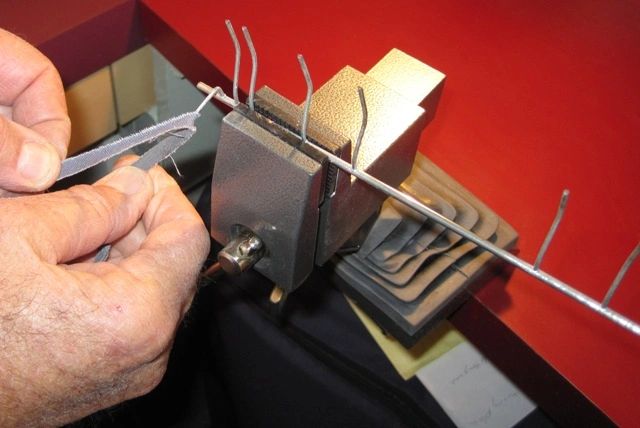
While you have your keys out is an excellent time to adjust your key tension, especially if high or uneven key pressures are making your accordion hard to play. Key tension is adjusted by bending the key springs. Grip the free leg of the spring as close to the coil as possible (but not through the coil) with needle-nose pliers and bend that leg with your fingers. Bend it toward the fixed leg to reduce the required key pressure; bend it away to increase the pressure. With the key below, changing the spring angle from about 90 degrees to about 45 degrees reduced the key pressure from 5 ounces to 2 1/2 ounces.

I have seen accordions requiring as much as 5 or 6 ounces to depress a key (very hard to play), but I prefer key pressures in the neighborhood of 2 1/2 to 3 1/2 ounces. I try to set the key springs to allow the key to start moving at about 2 1/2 ounces of pressure and to be fully open at about 3 1/2 ounces. Don't be tempted to reduce the pressure much below that, because weaker springs don't seal the valves as well and don't return the keys as quickly.
You can easily make a simple scale to measure key pressure. I used a weak coil spring that I made by winding .025" diameter stainless steel wire tightly around a 5/16" bolt. I used some recycled plastic parts to make my scale plunger and housing, but you can just as easily make yours from wood or metal. As the left end of the plunger presses on the key, the spring tends to resist the travel of the plunger through the housing. As the coil spring compresses, the length of the plunger emerging through the top of the housing is directly proportional to the pressure on the plunger. Lines marked around the perimeter of the plunger indicate how far the plunger has traveled relative to the housing, and thus how many ounces of pressure you are putting on the key.

You can use a postage scale to calibrate your scale in ounces, or you can calibrate it using the keys of an accordion whose key pressure you like, simply by marking a line on your plunger at the point where spring pressure of your scale begins to open those keys. I wrapped a gummed paper label around my plastic plunger, and marked my 2, 3, 4, and 5 ounce lines on that. My green housing is a plastic drive gear from an old fax paper roll, but you can use anything handy. Just drill a hole through it large enough for your plunger to pass with very little friction. A washer to retain the bottom of the spring, and a couple of wire pins installed through holes drilled through the plastic plunger complete the design.
To return to the table of contents for this page, click here.
WAXING WITH A WAX POT AND SPOON
In the accordion factories in Castelfidardo, they still wax reeds into the reed blocks with a wax pot and spoon. Prior to visiting there, I found it difficult to wax with a spoon, and preferred to use an eye dropper. However, the eye dropper is not without its problems, most notably the frequency with which it clogs up with wax that cools within it. I was therefore quite happy to observe and learn how to properly use the spoon. Properly used, it is a fast and convenient way to wax reeds into their reed blocks.

Think of the spoon as a fountain pen. The flat sides of the spoon are its reservoir, and the forward point is the pen point. Heat the spoon in the wax pot until it matches the temperature of the wax. This takes only a few seconds. Withdraw the spoon, shake off some of the excess wax with one quick, light shake, and immediately rotate it to the horizontal. In this position the wax adheres to the sides of the spoon. As you rotate the rounded edge up toward the vertical, the molten wax flows toward the straight edge on the bottom. As you tip the point downward, the wax flows along the straight edge toward the pen point. By coordinating this rotation and tipping you can precisely control the rate at which wax runs off the point. Use this "fountain pen" to "write" the wax onto the work. To stop the flow, simultaneously tip the point back up to level and rotate the spoon back to horizontal. When it runs out of wax, dip it into the wax pot again.
The people in the factories wax very quickly by rotating the reed block around in one hand to cause the molten wax to flow along the channels between adjacent reeds. This allows them to use the spoon at near maximum capacity. I have not yet developed this coordination skill, so I hold the reed block level and still, while I move the spoon along the channels, frequently rotating it around to deliver the wax at a slower rate. Even so, this is much faster than using the soldering iron with the modified waxing tip (see the article on waxing with a modified soldering iron).
For a wax pot I use a small (1 quart) electric "crock pot" slow cooker. I use the high heat setting initially to melt the wax, then turn it down to low. If left on high, my pot will overheat the wax, causing it to smoke as the more volatile compounds are driven off by the excess heat. If allowed to continue, this smoking would cause premature aging and embrittlement of the wax. The best temperature for the wax is around 220 degrees Fahrenheit. At this temperature it is thin enough to flow freely, yet not hot enough to smoke.
It is also hot enough to burn you pretty badly if you spill it on yourself, so be careful. And always keep in mind that wax is flammable. Keep open flames away from your wax pot.
I buy my reed wax already mixed in one pound bricks from Frank Romano of FRM Enterprises in Montreal for about $19 per pound. I think Frank currently has a $300 minimum order, so check his online catalog for other things you might need (he is a good source for high quality reasonably priced shoulder straps, bass straps, felt/leather valve facing material, and just about anything else you might need to repair your accordion). You can also mix your own reed wax. There are various formulas in use, but all are mostly beeswax, with varying percentages of pine resin and a small amount of linseed oil. I have no experience mixing my own, and therefore cannot advise you on the exact proportions to use.
To return to the table of contents for this page, click here.
MAKING AN OVER-SIZE AIR RELEASE VALVE
After playing a Giulietti or a Petosa with their relatively large air release valves which allow closing the bellows quickly and easily with a minimum of whooshing noise, I always felt rather let down to have to go back to a normal accordion with its pathetically small, slow, and noisy air valve. When I push that air release button I want instant results. So I enlarged the air release valves on all my favorite accordions. Now I can close my bellows quickly and quietly.
Open the accordion at the bass side, take out the bass reed blocks and set the bass cabinet bellows-side-down on the work bench. Remove the bass cover and locate your air release valve, button, and linkage. Examine both sides of the bass foundation plate right around the valve port, note any obstacles (reed block mountings, register slide linkages, bass strap adjustment screw, etc., and decide whether there is room to enlarge the valve, how much, and in which directions. Take into account the need for the linkage arm to reach across the center of the new larger pallet, and for the pallet to lift off its port when you push the air release button.

Scavenge a bass pallet from a junk accordion, strip off the old valve facing, wax, and glue, and reface it with new felt/leather laminate. See the article on re-valving for more specific instructions. Remove the old air release valve by twisting it off its linkage arm. Place your new valve over the hole in the position you want it to occupy, re-bend the linkage arm as required to fit, including a vertical jog if the new pallet is taller than the original, and trace the valve perimeter with a pencil. Take out the new valve and its linkage and mark the perimeter of the enlarged hole you want to make, keeping it a minimum of 1/8 inch inside the previous tracing, so your new valve will have at least 1/8inch bearing/sealing surface all around the new hole.
Use a round file such as a chainsaw file to enlarge the old hole out to your latest markings. Clean up all the sawdust, place the new valve into position, centered within its previously traced outline. Reinstall the linkage, check the height of the air release button, and bend the linkage arm as required to set the button at the correct height relative to the bass cover. Use your modified soldering iron to wax the pallet to its linkage arm (see the article on waxing with a modified soldering iron for more details).
Reinstall the bass cover, reinstall the bass reed blocks, reattach the bass cabinet to the rest of the accordion, and test the operation of your new air release valve.
The basics of this procedure can be used to add an air release button to an accordion that does not have one. In this case, you can either scavenge the linkage and button from a junk accordion and modify it to fit, or you can fabricate a new linkage assembly from scratch. If you fabricate from scratch, see the article on replacing bass buttons for tips on how to install the button onto your new linkage.
To return to the table of contents for this page, click here.
INSTALLING RHINESTONES ON BASS BUTTONS
Most accordions came from the factory with a dimple on the C button, but many of us also like some tactile identification of the Ab and E buttons. It is fairly easy to add rhinestones to these buttons. It is even easier to just dimple them, but I think it is useful to have a unique tactile cue on the C, so I generally use rhinestones on the other two.
To install a rhinestone you must first dimple the button by drilling a conical hole in the top of it, then glue a conical glass rhinestone into the hole, so if you want dimples, you just omit the rhinestones. Whatever the final goal, the drill tends to push the button down, so if the button is still mounted in the accordion, you need some way to hold the button up while you drill. I use a hemostat that I have modified to have a circular gripping surface to minimize damage to the sides of the button. I put the hemostat loosely in place, forcing some neighboring buttons down flush so the hemostat can lie flat on the bass board and grip the Ab or E button near the bottom. Then I clamp the hemostat in place to keep the gripped button from depressing.
On accordions it is always best to drill by hand. For most drilling I use a drill chuck taken from an old drill motor to grip the drill bit and I turn it by hand. For drilling bass buttons I have a modified (sharpened to 45 degree angle, rather than the standard 30 degree) 5/32" drill bit mounted rigidly in a brass knob, with a close fitting rigid plastic tube around the drill bit to act as a stop, allowing the drill to penetrate only to the depth of the conical back of the rhinestone. If you drill too deeply, the rhinestone might not stick up far enough to be noticed. The short piece of thin walled brass tubing fits over both the button and the plastic tube to keep the drill bit centered on the button.

Alternatively, I sometimes drill a small pilot hole in the center of the button, then enlarge the hole with the 5/32" drill bit. In this case the pilot hole keeps the drill centered.

Of course, all this is even easier if you have the piston out of the accordion, and it is not too hard to get them out, if you are so inclined. Just remove the note piston cap strip, as in the photo below, lift the desired piston out of its slot and fish it out through the top of the bass keyboard. It will take a little patience to get it back in and properly engaged with its bell crank lever, but the ease of drilling your button in a bench vise makes it worthwhile.


When I have drilled to the desired depth, I put a small drop of Superglue into the hole and set the rhinestone in place. In just a minute or two it sets and the accordion is ready to play. To minimize the chances of gluing your fingers together, it is a good idea to wear latex gloves when working with Superglue. I handle the rhinestones by sticking a small screwdriver to the top of the rhinestone with a bit of reed wax, leaving the conical bottom clean for best adhesion. I use a wooden toothpick to press the rhinestone down and free it from the screwdriver, then to clean up any excess superglue that oozes out from under the rhinestone before it dries.
I use 4.0-4.1mm Swarovski crystal rhinestones from Fire Mountain Gems. You can order online at firemountaingems.com. Order stock number H20-4835CY for clear, order stock number H20-4843CY for emerald. Other colors are available. They cost a little over a dollar for each package of 12, but the shipping on my last order was $7.65, so to minimize your average cost get lots of them. Use a 5/32” (4mm) drill bit (sharpened to 45 degrees) with a stop set to allow you to drill only as deep as the tapered point. This gives the correct angle and depth of hole to fit the conical back of the rhinestones.
Here is a nice clean installation.
To return to the table of contents for this page, click here.
Bellows tape serves to strengthen the bellows folds, protect the cardboard from abrasion, and enhance the appearance of the accordion. Keeping the bellows tape in good shape can prolong the life of the bellows. It is normally stuck to the underlying bellows fabric with a glue that allows it to be peeled off without damaging that fabric, so when your bellows tape becomes tattered and frayed, you can peel it off and replace it without destroying the bellows.
Replacing bellows tape is time consuming and therefore expensive if you have someone else do it, but it is not difficult to do yourself. Bellows tape is available in 19mm wide x 50 meter rolls in a variety of colors from Frank Romano of FRM Enterprises in Montreal, for about $36 per roll. I think FRM requires a minimum order of $300, so you will have to combine your tape order with some other items to make it economical, or find another source.
The first step is to prop the bellows open. Pull all the bellows pins (keeping them in order) and separate the bellows from the treble and bass cabinets, marking it as necessary to allow you to reassemble it in the correct orientation later. Cut two pieces of 1/8 inch plywood or masonite particle board about 3 inches wide x about 1/2 inch less than the outside width of your bellows. These should be made to fit snugly into the interior folds of your bellows, one at each end so they can be used to hold the bellows open while you work. Drill a 1/2 inch diameter hole at the exact center of each piece. Cut a piece of 1x1 wood molding about 14 inches long and make a tapered point on each end, to fit into the holes. Insert the plates into the last fold at each end of the bellows, stretch the bellows open, and insert the pointed rod into both holes. This should hold the bellows open while you work.


The second step is to remove all the old tape and glue. Slip a dull blade under the corners at each end of a tape to allow you to grasp the tape with your fingers and peel it off. Smooth the underlying surface as well as you can without damaging the underlying fabric, because any irregularities or lumps you leave will telegraph through the new tape.
Choose one side of the bellows to do on the first day. If you are not yet good at this, it might be wise to start with the back. Mark all the metal corners with a pen or with a straight row of short pieces of masking tape so you can keep the ends of your tape well aligned and flush with those markings. Cut your new bellows tapes to the right length to fit the folds on the bellows side you have chosen. Fold each tape in half the short way and put a firm crease down the middle of it to help keep it centered along the bellows fold. Lay five or six of the tapes out upside-down on a sheet of masking paper or newspaper and apply the glue to the tapes with a small brush.
Use the special bellows tape glue from FRM Enterprises, which is designed to release, making your bellows repairable in the future. If you use Elmer's or something similar, the next time someone needs to change a metal corner or repair your tape, they will not be able to do it without damaging the bellows fabric and perhaps even the cardboard, and that will be the end of the bellows.
Using the creases as your guide, center the first tape on a bellows fold with both ends aligned with your markings on the metal corners and press it firmly into place, using a damp cloth between your fingers and the tape. The tape will tend to flex back open until the glue begins to set, so you may have to repeat this a few times until it finally holds. When you have the first five or six tapes installed in this manner, run the damp cloth over them all once more to wipe away any excess glue, and repeat the process with five or six more tapes. When you have all the tapes installed and all the excess glue cleaned off, remove your interior props, close the bellows, and place a 30 pound weight on it (another accordion in its hard case works well), and let the glue cure overnight. The next day repeat this process for the next side and so on until you have all four sides done.
You will notice that the end folds are a special case. These folds (like all the rest) were taped before the bellows was glued to the bellows frame, so nearly half the tape is stuck in the glued joint and will have to remain there. You cannot pry this joint apart without destroying the bellows. The best you can do is to cut these tapes a bit narrower and tuck one edge of the tape as far down into the glued joint as you can without damaging the joint. Alternatively, if the tape on these folds is not damaged and if you are re-taping with the same color tape, you might consider leaving the end folds alone.
If you want to put a design into your bellows tape with a contrasting color, install the design first, using short tape segments, then cut your regular tape to length to fit all around it (butting up to it) and install that last. Do not install the design on top of your regular tape, as this double taping will thicken your bellows so your bellows straps will no longer close.
New bellows tape can be applied over old bellows tape, and wider than normal tape (24mm wide) is made for this purpose. However, if you take this shortcut you will have to move your bellows straps and/or snaps, or replace them with longer straps. In that case, you will have some old screw holes to fill, including repair of the celluloid finish. For suggestions on how to do that repair, see the article on repairing stripped out screws.
To return to the table of contents for this page, click here
REPLACING BASS BUTTONS
It is not unusual to have to replace a bass button or two. Some prior owner may have butchered the button trying to mark it in some way. I have seen them with notches sawn into them apparently with a hacksaw, creases melted into the top apparently with a hot knife, and even with one side melted away where some misguided soul apparently touched it with a hot soldering iron. I have seen oversize jewels glued on top, and huge dimples drilled into the wrong buttons. I have also seen several buttons scratched and scraped, apparently by sliding on concrete or asphalt. Whatever the problem is, it can usually be solved by replacing the button.
If your buttons are black, finding a matching button will be fairly easy. Just make sure you get the correct diameter. The height is not so critical, as the depth of the piston insertion into the button can be varied to make up the difference. If your buttons are red, gold, or some other color, getting an exact match will be difficult. Cerini in Castelfidardo sells new buttons, and so does FRM Enterprises in Montreal, but color choices are limited. Look first to any junk accordion you or your local repairman might have lying around. Junk accordions should never be thrown away, as they are excellent sources of hard to find parts and materials, including bass buttons.
Once you have your replacement buttons in hand, disassemble your bass machine to the extent required to extract the pistons with damaged buttons (see the article on disassembling and reassembling bass machines). Carefully measure the overall length of the piston/button assemblies so you will be able to push the new buttons onto the pistons just far enough to match this overall length for each piston.
To remove the old button, hold the piston with the damaged button in the fingers of one hand and twist and pull the button off with the other hand. If it will not come off, clamp the piston into a bench vise, or into a vise-grip pliers, which in turn is to be clamped into the bench vise (taking care not to bend the piston or to damage any if the pins or dogs pressed or stamped into the side of it), and heat the side of the piston with a soldering iron until the plastic or glue begins to soften just enough to allow you to pull the button off.
Once you have the old button off, measure the diameter of the end of the piston that must go into the new button. Drill or ream the pilot hole in the bottom of the new button to exactly this diameter if you intend to glue it, or to just a few thousandths of an inch smaller if you intend to weld it (that is, if you intend to heat the piston to the melting temperature of the plastic button and force it into the pilot hole in the button, so that as the melted plastic around the pilot hole cools, it will adhere to the piston). In either case, drill or ream your pilot hole to a depth 1/16 inch greater than that theoretically necessary to allow pushing the piston into the button far enough to make the new assembly exactly the same length as your pattern. This allows room for some small amount of plastic or glue that may be pushed to the bottom of the pilot hole by the advancing piston.
Whether you choose to glue or weld, the next step is to install the button onto the piston, taking care to make the overall length exactly match your previous measurement. When the plastic cools, or the glue dries, as the case may be, reassemble your bass machine, taking special care to ensure that every button goes exactly back where it came from and that every pin or dog on each piston properly engages its bell-crank levers. Reinstall the bass reed blocks, the bass cover and the bass strap, and reinstall the assembled bass cabinet onto the bellows. Check the bass machine for proper operation to make sure no buttons are sticking and all chord buttons are playing all the correct notes.
To return to the table of contents for this page, click here
For various reasons, you may have to remove or disassemble a bass machine. For instance, if one or more bass valves is leaking and you are unable to solve the problem working from the reed block side, then the bass machine will have to be totally removed to gain access to the bass valves. If your bass machine is not removable as a unit, then you will have to disassemble it piece by piece.
Other problems that can require at least partial disassembly of the bass machine include a bass valve hanging open due either to sticking "pipes" (bass valve bellcranks), worn cam levers on the pipes, or worn valve lifters (cam followers) on the valves. You might also encounter a broken actuating lever on one of the pipes, cracked or broken wood mountings for the bass machine, or pistons bent too badly to straighten without removing them first.
Whatever the reason for disassembling your bass machine, you must make sure that you will be able to put it back together correctly, as each of the (usually 120) bass button pistons and each of the (usually 24) pipes is unique, and must go back in its original position.
The easiest way to do this is to make a rack to hold the bass button/pistons in their proper positions relative to one another as you take them out. I drilled seven rows of twenty holes in three pieces of plywood that I then stacked with spacers between, to provide a separate chamber for each button from any accordion up to 140 bass. An easier way, if you have a junk accordion, is to salvage and use the bass keyboard, which already has the 120 holes drilled in it.

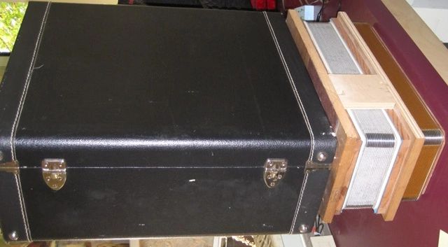
After you remove your bass strap and bass plate, your bass machine should look something like this.

Before you begin the disassembly, take a few moments to observe how your bass machine is constructed and how it works. This will help you understand how to keep its various parts in order and how to put it back together. By observing and understanding, you will also learn some things about accordion design and how the bass machine is really a simple mechanical computer that assembles chords on command. After going through this little exercise, whenever you look at a bass machine you will see order and symmetry and an elegant design, rather than the chaos and unfathomable complexity that you may be seeing now.
Take your time.
Relax.
Get in touch with yourself and your machine. It is a beautiful machine that makes beautiful music, and in a few moments you will understand how it does it.
With the bass cover off, push any bass chord button and observe that the button is on the top end of a long piston which has three pegs or tabs along one side of it (some older accordions have four pegs or tabs on their seventh chord pistons). Observe that each peg contacts a lever and forces that lever to move with the piston. Observe that there are four neat rows of levers, all lined up with four neat rows of pegs on the pistons.
Notice that the bottom end of the piston passes through a slot in a wooden guide, and that the bottom of the piston has a sharp 90 degree bend to prevent the piston from coming out of the slot when valve spring pressure forces the piston upward as you release the button.
Rest the tip of a small screwdriver or similar tool against the bottom end of the piston (90 degree bend) and rest your finger on the button at the top end. Rock the piston gently up (toward the button end) and down and notice that there is a small amount of clearance between each peg and the lever it engages, and that you can therefore rock the piston up and down by some slight amount without causing any levers to move.
Notice that each piston has four possible locations for pegs or tabs, that only three of them are used, and that the position not occupied by a peg varies from piston to piston. As you peer down into the bass machine, notice the other tiers of pistons nestled beneath the top tier. Also notice that every second piston (button) in the top tier passes through a hole in the diminished chord row of the bass keyboard, and that the ones in between pass through holes in the seventh chord row. Notice that in the second tier down, every second piston (button) passes through a hole in the minor chord row, and that the ones in between pass through holes in the major chord row. Notice that each piston has a slightly different bend in it in order to accommodate this arrangement.
Looking farther down inside the bass machine, you can see a tier of longer pistons with its own slotted wooden guide, and you will notice that every second piston (button) in this tier passes through a hole in the fundamental bass row and the ones in between pass through holes in the counterbass row.
As you press one of these fundamental bass or counterbass note buttons, you will observe that the single peg (or tab) on the side of its piston engages a single lever and causes it to move with the piston. Notice that the bottom end of that lever is fixed to one of 12 slender steel rods (technically bell cranks, but commonly called pipes) lying under the pistons, and that this pipe rotates when the lever moves. With a bright light illuminating the area directly under these pipes, observe that as the pipe rotates, one of the 12 note pallets lifts, opening a note valve, and as it opens it also lifts an adjacent chord valve pallet.
Find the fundamental bass note button (not the counterbass button) that opens the valve at one end of the pipes (where it is easiest to see) and observe that the pipe has a short cam lever on it that lifts a cam follower on that note pallet arm, opening the note valve as the pipe rotates. Notice that the note pallet arm extends past the end of the pallet and engages the underside of a similar extension on the chord pallet arm, causing the chord valve to open whenever the note valve opens.
Now press the major chord button next to that same fundamental bass button, and watch the chord valve open while the corresponding bass note valve stays closed. Do the same, one at a time, with the minor, seventh, and diminished buttons in that same diagonal row of buttons (chord family). Notice that in each case the first pipe rotates, forcing its cam lever to lift the chord pallet, thereby opening the chord valve, and realize that this chord valve is for the root note of all the chords in this chord family. Understand that this particular pipe and its cam lever, along with two of its levers that engage pegs on these four pistons, cause the bass machine to play the root note whenever you push one of these chord buttons.
As you press each of these chord buttons a second time, use your bright light to observe which other two valves open, along the row of 12 chord valves. Understand that these other two valves are the other two notes that join the root note to make up each of these chords.
Observe that each valve is operated by only one cam lever and pipe, but that each pipe has many levers on it, each extending upward to engage a peg on the side of a chord piston that uses that particular note. Focus on just one of these pipes for a moment. Push one of its levers downward (away from the bass buttons) and observe how many other levers move with it, and which pistons have pegs that engage these levers. Whenever any one of those particular chord buttons/pistons is pushed, one of the pegs on the side of its piston engages one of the levers on this pipe, causing this particular pipe to rotate and the valve it controls to open. The other two pegs on that piston each engage a lever protruding from one of the other two pipes whose notes comprise the chord played by that button.
Notice that there are 12 chord valves and 12 chord pipes, and that there are also 12 note valves and 12 note pipes. The note pipes operate the valves that control the two lowest octaves in your bass reed set, while the chord pipes operate the valves that control the (usually two or three) higher octaves. Each pipe in each set of 12 pipes is dedicated to a single note of the 12 note chromatic scale. Chords are played by rotating three pipes simultaneously, thus opening three separate valves. The bass machine assembles chords for you by opening the three correct note valves whenever you press any single chord button.
Just as the chord valves and note valves are arranged in your bass machine, so are the reeds arranged in your bass reed blocks, because directly behind each valve lie the reeds for that note. Therefore, if your chord valves line up with your note valves (on some Russian accordions they don't), then all the reeds for that note line up across the various reed blocks. In other words, if the first reed in one reed block is Bb, then the first reed in each of the other reed blocks is also Bb, although in another octave.
You can use this knowledge to determine how the bass reeds are organized within each reed block. Some accordions have their bass reeds organized in chromatic scale order, while some have them arranged in accordance with the circle of fifths. You can easily determine which system you have by observing the operation of your bass machine.
Press your C note button and observe which valve opens. Now press the F or the G button. If a valve right next to the C valve opens, your bass reeds are arranged in accordance with the circle of fifths. If you must press a B button a C# button to get this valve to open, then your bass reeds are arranged in chromatic scale order. Either way, by identifying which button operates the valve at each end of your 12-valve array, and therefore which note lies at each end of the row of valves, you can now fill in the names of all the notes in between. With this knowledge, you can see which three notes are being played by each chord button.
This is academic, I know, but if you have gone this far, and used your knowledge of the bass machine to deduce the arrangement of your bass reeds and to determine which notes comprise each chord, then you are to be congratulated for being truly in touch with your machine. You can now safely disassemble your bass machine with confidence that you will be able to get it back together correctly, so let us begin.
In order to get the pistons out, you must first remove the cap strip (usually wood) over the guide slots at the bottom of the pistons. It is usually held in place by four or five small brass wood screws. Removing this cap strip allows the diminished and seventh chord buttons to be lifted out of their slots. Pull the buttons down into their holes as you remove the pistons one by one and place them in your rack. However, the minor and major chord buttons cannot be removed until first removing a thin plastic barrier that rests in a slot in the button side of the slotted wooden guide. Sometimes this plastic separator is held in place by several short narrow strips of plastic glued across the outside of the slot. In other cases it is held in place by tiny nails or by friction alone.
When you get all the chord buttons out, you will have to remove their slotted wooden guide, which is held in by two large wood screws, one at either end. Once this is out, you will have access to the note buttons, which are retained by their own separate cap strip, which also must be removed. In most accordions it is easier to take the note buttons out through the top of the bass keyboard rather than pulling them down into the accordion.
Once all the buttons are safely in your rack, you can remove the pipe retainers, usually including a flat brass or aluminum strap across each end of both sets of pipes (chord set and note set) and two bent wire retainers in between. The straps and wire retainers are anchored by small brass wood screws.

Before removing the pipes or disturbing their order, take note of the logic of their arrangement. You will be removing and storing the pipes in order, but in case they get mixed up you want to be able to get them back into the proper order. There are two common arrangements for the chord pipes, one for accordions with their bass reeds laid out in the reed blocks in accordance with the chromatic scale (by far the most common) and one for those with their bass reeds mounted in accordance with the circle of fifths.
In accordions with their bass reeds arranged in accordance with the chromatic scale, you will see that the chord pipes are arranged in order of the position of their cam lever along the pipe, which puts the pipes in the same order as the reeds. Usually, the pipe that opens the valve for the first reed in the reed block goes in first. It has its cam lever (which actually lifts the valve), at one end of the pipe. The pipe that opens the valve for the second reed in the reed block goes in second. It has its cam lever (which actually lifts the valve), a short distance from the end of the pipe. As you ascend the chromatic scale (and travel along the reed block and the associated row of bass valves), each successive chord pipe cam lever is located just a bit farther from the end of its pipe, because the valve it opens is just a bit farther down the line of valves. The last cam lever opens the last valve in the row. The cam levers line up like stair steps along the row of valves, the first cam lever opening the first valve, the second cam lever opening the second valve, and so on, with the last cam lever at the opposite end of the pipe opening the last valve.
The note pipes might be arranged slightly differently. While still generally in chromatic scale order, part of the order may run up the scale and part of it may run down. For instance, in one I recently had apart (see the photo immediately above), the first five note pipes operated valves 1 through 5, then the sixth pipe jumped to valve 12 and from there the sequence continued backwards down through valve 6.
In accordions with their bass reeds arranged in the reed blocks in accordance with the circle of fifths (i.e., in the same order as the bass buttons) the pipes are arranged differently, in the order required to put the notes back into chromatic scale order. In other words, the first pipe opens the first note of the chromatic scale, and the second pipe opens the second note in the scale, just as before, but the second note in the chromatic scale is not the second valve in the row. It is located farther along the row, and so its cam lever is located farther down the pipe. It is not nearly as easy to visually determine the proper order of the chord pipes in this arrangement, because the cam levers do not line up like stair steps.
The important thing is to recognize and remember the proper order, or at least be sure you can figure it out logically, because there are about 479 million possible ways to put them back (the number of possible 12-permutations of 12 = 12! = approximately 479 million). If you put them back in random order, the odds are about 479 million to 1 against you getting the right order on the first try. If you try 1 permutation every 3 minutes, working 8 hours a day, 5 days a week, 50 weeks per year, you will try 40,000 permutations per year and it will take you 9,475 years (over 100 lifetimes) to try all the possible permutations. So before you take the pipes out, make sure you understand how they must go back in.
Here is your disassembled bass machine:

Getting the pipes out of order is not a problem with accordions with removable bass machines, because the entire bass machine, buttons and all, and sometimes even including the bass board, is fastened in with just a few screws or clips, sometimes as few as two. Remove these few screws or clips, lift out the bass machine as an assembly, and you have instant access to the bass valves.
Once you have finished your work on the valves, you will have to reassemble the bass machine. If your work included re-valving, you will have to set up the bass machine as you assemble it. Setting up the bass machine involves setting the bellcrank actuating levers at the proper angle to engage the pegs on the sides of the pistons with a minimum of lash, but not zero. Instructions for setting up the bass machine can be found in the article on re-valving the bass side.
To return to the table of contents for this page, click here
New bellows are so costly that we rarely replace them unless we have to. But replacing them can help make your old accordion look and feel like new, and you can minimize the cost by doing it yourself. Just cut the old one off and glue the new one on.
However, don't get in a hurry to cut the old bellows off just yet, because it takes two or three months to get a new one made and delivered. Measure the length, width, and depth of folds of your old one precisely in millimeters. Give the bellows maker those measurements along with the number of folds, the metal corner style number, and the colors you want for the leather corners, the bellows fabric, and the bellows tape. I get mine from Fernando Marconi in Castelfidardo.
You have to reuse your old bellows frames because they were custom made to precisely fit your treble and bass cabinets. Once you have the new bellows in hand, use a box cutter to cut the old bellows off your old bellows frames, but not before marking each frame on its front side so you will be sure get them both installed in the proper orientation on the new bellows. Cut the cardboard as close to the wooden bellows frames as possible without damaging the wood.

The hardest part of the job is scraping the remaining cardboard and glue off the bellows frames. You want to get down to the bare wood to ensure a flat mating surface and a strong glue joint between the old bellows frame and the new bellows. You can sometimes speed up this process by applying a bit of heat to the old glue. A heat gun is not advisable because you risk melting the plastic trim around the bellows frame, so I made a copper scraping tip for my 30 watt soldering iron ($5 from Orchard Supply Hardware). It is constructed very similarly to the copper waxing tip I made for my 15 watt soldering iron, except I used a heavier gauge of copper for the scraper.

If heat does not soften your glue, you will have to scrape it off the hard way, with a box cutter and a lot of elbow grease. In that case, expect to spend two to three hours scraping. Once you have them clean, get them both oriented with their previously marked fronts pointing in the same direction, and make sure the bellows is going to be a good fit. Glue the new bellows onto the frames one at a time as follows.
Paint Elmer's white wood glue onto the mating surface of one of the bellows frames with a small brush. Make sure you get a good even coat all over the mating surface, then add a small bead all the way around on top of that without brushing it out. You want just enough glue so that it slightly oozes out all around when you put the bellows on, but not so much that it runs out and makes a mess.

With the bellows frame lying flat on your work table with the glue side up, set the new bellows down on it ensuring that you have it perfectly centered. Press it lightly down and with a damp rag wipe off any excess glue that appears from the joint.
Place a 30 pound weight on top of the bellows (I use my test bellows, which has a heavy box of bolts inside, with an accordion on top of that), and let the glue dry for at least two hours, continuously cleaning off any excess glue, taking care not to wipe it into the bellows folds.
After two hours, remove the weights, carefully turn the bellows over, and repeat the process for the second bellows frame, taking special care to get the marked front sides of both bellows frames pointed in the same direction. This time leave the weights on overnight. In the morning you will be able to install your new bellows and immediately start breaking it in.
To return to the table of contents for this page, click here
RE-VALVING THE BASS SIDE AND SETTING UP THE BASS MACHINE
If you determine that your bass valves are leaking, check first to see if some foreign object might be lodged under any of the valves (see the article on finding leaks). Next, check to see if any of the bell crank (bass pipe) levers are resting tightly enough against their piston pegs to keep a valve from firmly closing. Often, these two steps will reveal the problem. However, it is not uncommon to find bass valves leaking due to deterioration of the felt or leather, due to poor alignment at the factory, or due to some kind of structural failure of the mounting of the pallet arms. The following photo, shows a failed glue joint, which allowed spring pressure to arch the hinge bar upward, putting three pallets out of parallel with the foundation plate and causing those three valves to leak.

For leaks caused by valve misalignment or deterioration, you will have to remove the bass machine in order to gain access to the valves. Unless you have a removable bass machine (perhaps 5% of accordions have them), you will have to disassemble the bass machine piece by piece and remove the pipes one at a time. See the article on disassembling the bass machine for instructions and an important warning about keeping the pipes in order.
Once your bass machine is totally out of the way, you can remove the pallets, but first close all the slides you can, and protect the slides and the remaining open ports with a small sheet of paper that you can move along as you twist each of the 24 pallets from its pallet arm. Catch as much of the crumbling wax debris as you can, in order to prevent it from falling into the slides or down into the reed blocks. When you have all the pallets out, set the accordion back upright (resting on the bass section) and shake out whatever debris you missed. At some point you should also remove the bass reed blocks and shake them out because some debris probably got into them.

Strip the old valve facings off the pallets and scrape off the old glue. Measure the thickness of the old valve facings and procure some new valve facing of the same thickness (I get mine from FRM Enterprises in Massachusetts). Use your roller cutter to cut strips of valve facing one note pallet wide and do the same for the chord pallets. Then cut individual valve pads from the strips, 12 to fit your note pallets and 12 for your chord pallets. Glue the new valve pads/facings onto the pallets and set them aside to dry. Use a thin coat of glue to prevent any of it from soaking into and hardening the felt.


Check all pallet arm hinge points and hardware for security and proper alignment, repairing any loose or misaligned mountings. Make sure all pallet arms rotate freely on their hinge points. Bend all pallet arms as necessary to exactly center them over their ports, taking care not to over-stress the pallet arm hinge points. In other words, support the pallet arm with one bending tool while you bend it with another. The goal here is to center the pallet over the ports, and since the pallet arm rests in the groove along the centerline of the pallet, centering the pallet arm is an essential step.

This is your best chance to resurface the cams and cam followers to ensure smooth operation. Don’t skip this step, because re-valving always results in slight changes in pallet height and thus in the height of the cam follower. This means the cam will strike the cam follower in a slightly different position and from a slightly different angle than it did before. Decades of use have created a unique wear pattern on the mating surfaces of each cam and its cam follower, and changing the pallet height alters the relationship that created this wear pattern so the surfaces no longer mate properly. This results in noisy operation and high friction that can cause valves to stick open. The remedy is to grind these worn mating surfaces smooth with fine emery cloth and polish them with crocus cloth. Check them with a magnifying glass under a bright light to verify that you have both surfaces smoothly polished.
Polishing a cam

Polishing a cam follower
Once you have the cams and cam followers sanded smooth and brightly polished, set all pallets in position, trimming any corners as necessary to ensure clearance between the pallet and the surrounding structure. Use a pair of bending tools to bend the pallet arms as required to make them lie flat in their pallet grooves (avoid putting too much stress on the pallet arm hinges and mounts). Significant bending of these arms will be required if your new valve facings are not exactly the same height as the old. Remove the pallets to verify that all pallet arms are still centered over their ports, and correct any mis-alignments.
Reinsert the pallets under the pallet arms, place the springs in position over the pallet arms, and verify that none of the note pallet arms are contacting the underside of any of the overlying chord pallet arms. During play, the note pallet arms will lift the chord pallet arms, but you want a small amount of clearance between them to ensure that the chord pallets will rest firmly closed until their corresponding note buttons are pushed. A few thousandths of an inch is all the clearance you need. If you can see the note pallet arm move at all before it contacts the underside of the chord pallet arm, or if you can hear a faint click as the rising note pallet arm contacts the underside of the chord pallet arm, you have enough clearance.
With all adjustments made, it is now time to wax the pallets to their pallet arms. Use the modified soldering iron to apply enough heat to make the wax flow all around and under the pallet arm and down into the groove, but not so much that the wax flows down over the side of the pallet (see the article on waxing with a modified soldering iron). Press down evenly on the pallet to ensure that it lies flat on the foundation plate as the wax solidifies.

When the wax and the pallet arms have cooled, check again to make certain that no note pallet arms are contacting the undersides of their overlying chord pallet arms. Bend the ends of the chord pallet arms up as required to obtain a few thousandths of an inch clearance. Also check for leaks before you reassemble the bass machine. One way to check for leaks is to place the accordion on your workbench accordion stand (see the article on disassembling the accordion for some tips on making a workbench accordion stand) and lift the bass section to expand the bellows. Let the bellows close under the weight of the bass section plus some moderate pressure from your hands and listen closely for leaks as the bellows closes. If you push down very hard, you can cause air pressure in the bellows to force the bass valves open on any accordion, but they should stay closed under a few pounds of pressure, such as in normal playing.
Another way to check for leaks, working from the reed block side, is to remove the reed blocks and check each valve with a paper feeler gauge. If you don't feel significant and uniform friction all around the edges between the leather valve facing and your feeler gauge, the valve is not seating properly.

Check very carefully for leaks, because this is your last chance to correct any problems before assembling the bass machine. Detecting a leaking valve later could cost you half a day's work to disassemble and reassemble the bass machine again in order to gain access to your leak.
Don’t be discouraged if you find some leaks. It is common for the wax to shrink as it cools, lifting one end or the other of the pallet. The remedy is simple. Use your modified soldering iron to melt the wax again, taking greater care this time to keep the pallet lying flat while the wax cools. As a final check before reassembling the bass machine, check for uniform pressure and friction under each end of each pallet with a paper feeler gauge. A strip of paper ¼ inch wide by 4 inches long works well. Do not install any pipes until you are satisfied that all pallets sit flat and evenly firm against the foundation plate, and that there are no leaks.
It is best to let the new valves rest on their seats under spring pressure at least overnight to allow most of the initial compression to occur prior to assembling and setting up the bass machine. Setting up the bass machine means adjusting the clearance between each of the pipe levers and the piston peg that drives it. No matter how carefully you have tried to match your new valve facing material to the original, it is bound to be of at least slightly different thickness. This means that even if the bass machine was perfectly adjusted before, it will be out of adjustment after installing the new valve facings. The initial compression of the felt or foam cushions will also alter the adjustment.
When you are satisfied that the initial valve compression has occurred, that all pallets are lying flat and tight against the foundation plate, and that you have no leaks, reinstall the note pipes in proper order, making sure that the lifting cam on each one fits under the cam follower on the pallet arm. Check each one for smooth operation before installing any pistons.
Install the note button/pistons one at a time, making sure at each piston that none of its pegs contact their bell crank levers when the lifting cam is touching the underside of the cam follower on the pallet arm, as this would eventually cause the corresponding note pallet to leak. Provide some clearance between the peg and the lever as follows.
You can save time and minimize the amount of bending by first bending the lifting cam lever (the single short lever that contacts and lifts the cam follower on the pallet arm) on each pipe to provide minimal lash at the first lever you adjust on that pipe. Bending the lifting cam to put the first lever into proper position relative to the piston peg should put all the other levers on that pipe in pretty close adjustment also. For minor adjustments of subsequent levers on that same pipe, bend the lever rather than the lifting cam. Bending the lifting cam later would put all the previously adjusted levers on that pipe out of adjustment.
You must maintain at least some minimal amount of lash (clearance) between each of the pegs on the side of the piston and the lever it will contact when that button is pushed. However, don't allow too much clearance, as this could cause the button to rest lower than the others and might cause some notes of a chord to sound later than others. Barely perceptible clearance is enough. A 50th of an inch (1/2 mm) is about the most you should allow.
You control this clearance by slightly bending the lever while preventing the pipe from rotating. You can prevent the pipe from rotating by firmly holding two or three other levers on the same pipe. I use 4-inch long pieces of 1/8-inch o.d. steel tubing (automotive brake line) slipped down over the levers as bending tools. Pushing two or three levers in one direction while pushing one lever in the opposite direction should cause the one to bend, but sometimes one of the others bends, too, and if this is one you have already adjusted, it will now be out of adjustment. For this reason, you must check the clearance at each peg and lever a second time, after all levers are initially adjusted.


A further complication stems from the fact that if one lever is too tight against a piston peg, it will hold the bell crank (pipe) in such a position to create clearance at all other levers on that pipe. When you go back and properly adjust the tight one a bit farther from its peg, it allows all the other levers on that pipe to rotate closer to their pegs. If that rotation exceeds the clearance at one of those pegs, that peg will now be too tight. When that one is eased, another may become too tight. You may have to chase these diminishing clearances back and forth along the pipe to make certain none of its levers are tight against their pegs. This is extremely important, because as the new valve facings compress slightly over time under spring pressure and the impact of repeated closings, the clearance in the linkage will be slightly diminished. If there is no clearance to begin with, the compressed valve will not seal, and you will have an external leak.
Once all the note pistons are installed and their levers are adjusted, install the wooden cap strip onto the slotted guide. Warning: if any of the cap strip screw holes have stripped threads down inside the slotted wooden guide, do not force the next larger screw size into the hole, as this will probably crack the wood and bulge it into one of the slots, causing that bass button to stick. The best way to repair a stripped screw hole is to glue in a soft wood plug and tap new threads into that. The softer the wood, the smaller the risk of splitting the slotted guide when you thread the screw into it.
You can help prevent splits by temporarily supporting the segment holding the screw. Wedge thin plastic strips alongside the pistons in the slots on each side of this segment while you drill your pilot hole and tap in the new screw. Or take those pistons out and fill the slots snugly with wood or plastic plugs. But don’t force your plugs in too tightly, or that, too, might crack the slotted guide. Even with this support you must be very careful not to split the wood. If it splits despite your best efforts, you will have to glue and clamp it back together, then use a thin metal file to clean the affected slot as required to allow the piston to move smoothly through it.
Once the note piston cap strip is securely in place, install the slotted wooden guide for the chord pistons and install just the major and minor chord pistons. Naturally, you must adjust the clearance between each of the piston pegs and its lever as you go. Once again, you can save time by bending the lifting cam on the pipe to set the proper clearance at the first lever on that pipe. That should put all subsequent levers on that pipe into pretty close adjustment so relatively little bending will be required on those subsequent levers.
Once all the major and minor chord pistons are in, install the plastic separator strip in the slot in the button side of the slotted guide and secure it with the little plastic tabs glued over the slot (or with screws or nails if that is how it was initially secured). Take special care not to drop any of the plastic tabs, as they will fall down between and under the pistons and will be very difficult to retrieve. You won't want to leave them down there, either, as they could lodge under a valve and cause a leak. When the plastic separator is secured, install the seventh and diminished pistons, adjusting the levers for each as you go, then finally the wooden cap strip.
It is a good idea to check for leaks at every stage; after the pallets are waxed in, after the pipes are installed, after the note pistons are installed, after all the major and minor chord pistons are in, and again at the end. This way, if you detect a leaking valve somewhere along the way, you will know that you caused it during the current assembly stage, making it far easier to find and correct the problem.
With your bass machine reassembly and setup complete, it is time to reinstall the bass cover, making sure to guide the air release button through its hole as you go. Install the bass cover screws, re-secure the bass strap, and play yourself a congratulatory song. By properly setting up your bass machine, you have just completed one of the more challenging accordion repair tasks. For even more challenging accordion repair task, see the articles on "Sorting out mixed up bass pipes" and "Sorting out mixed up bass buttons."
To return to the table of contents for this page, click here
Whenever we must get access to the bass valves, we really appreciate having a removable bass machine, because it saves us the work of removing 120 bass buttons one at a time, their supporting structures piece by piece, and all 24 bass pipes one at a time, just to get at the valves. Instead, we just remove two to four screws, or sometimes just release two spring clips, and… voila! The bass machine slips right out and we have instant access to the valves.
Here is a photo of one with just two brass clips holding the bass machine and bass plate in place.

Here it is again with the clips released.

Now the bass machine is slid partly out of the accordion.

And it’s that simple. We now have access to the valves.

When finished working on the valves, just slide the bass machine back into position and snap the two clips in place. Now, that’s the way to design an accordion.
To return to the table of contents for this page, click here
Sorting out Mixed up Bass Pipes
If you or a previous owner have disassembled the bass machine and got the pipes out of order, and if you do not know the proper order, you have a serious problem. Because there are so many different possibilities (12! = just over 479 million for the note pipes and another 479 million for the chord pipes), you can never hope to get it right through random trial and error. To have any hope of success, you must deduce their proper order, which may not always be possible.
Start by sorting the note pipes separately from the chord pipes. This is simple because each note pipe has three or four short levers in addition to the cam lever, while each chord pipe has many more and much longer levers.
Next, determine the order of the reeds in the bass reed blocks by sounding them and naming their notes. Label each valve (directly under each reed you identify) with the name of its note. If the reeds and valves are in chromatic scale order, then you can assume that the note pipes must be arranged basically in the order of the positions of their cam levers along the pipe. That is, the one with the cam lever nearest to one of the ends will go in first, under the shortest valve arm, the pipe with its cam lever second nearest to that same end will go in second, under a slightly longer valve arm, and so on. However, as described in the chapter on disassembling the bass machine, in some accordions there are some discontinuities in that order, and some sections may even be in reverse order.
These discontinuities will become obvious when you come to a valve whose cam follower lever is not long enough to reach out over the cam lever on what you might expect to be the next pipe. At this point you will have to find another pipe whose cam lever is properly positioned to lift this cam follower. In fact, you may have to back out a few pipes to find the correct new starting place.
This would be a good time to look for evidence of wear on the underside of the valve lifting arms, which if present will tell you where the cam levers formerly contacted them. Use a light and a small mirror to examine the undersides, and mark the location of the worn area on top of the arm with a pencil or a permanent marker. If you are lucky enough to find such wear, then your puzzle is solved. All you have to do is install each pipe in the position that will cause its cam lever to contact the underside of the valve arm at the old wear point.
If the accordion is new enough that no wear is visible, then at this point you will be faced with some inevitable trial and error. However, you should always be focused on the big picture, looking for the right new pattern and the proper place to begin that pattern, rather than trying random pipes. The point is, there is definitely a pattern; the arrangement is never random. The notes will be sequential in chromatic scale order, either up or down, possibly with some discontinuities and possibly with some segments progressing up the scale and some progressing down the scale.
Labeling each of your remaining pipes with the name of its note will help you recognize and continue patterns. Each of the twelve pipes (whether note pipes or chord pipes) has its one and only cam lever positioned along the pipe so it can only reach one valve lifting arm, and that valve lifting arm is on the valve for that pipe’s note. Since you already have the valves labeled, matching the pipes with the valves is a simple matter. The only hard part is labeling them because they are so small. I use a piece of masking tape stuck to one of the pipe’s levers like a flag.
Once you recognize the pattern developing in the order of the pipes, it will be simple to select the next pipe to install, at least until you reach another discontinuity and must discover the new pattern for the remaining pipes. If you fail to discover the pattern, you will have no real hope of ever getting it back together properly.
If the reeds are mounted in circle of fifths order, you can still assume that the pipes will be in some kind of chromatic scale order, but you will also know that they will not be in the order of the positions of their cam levers along the pipe, which makes it much more difficult to visually identify the pipe that belongs in any given location. As in the process for chromatically ordered reeds and valves, you will have to label each of the valves with the name of its note, then find the pipe that has its cam lever correctly positioned to open this valve, and label it, too. You still don’t know which pipe goes in first, but figuring that out will be comparatively easy, as there are now only twelve possibilities.
Start by comparing the lengths of the cam follower arms mounted on the bass valves. Obviously, they have to reach out over the assembled pipes far enough to reach the cam lever on the pipe for that note. A very short cam follower arm means the pipe containing the cam lever that will open that valve cannot be too far away. A very long cam follower lever indicates that its pipe is probably farther out. Unfortunately, there may be some ambiguity due to the fact that accordion manufacturers do not always trim off the cam followers at just the right length. Some are left a bit longer then they need to be.
Note that some of the valves have their cam follower levers pointing the opposite direction, but the same principle still holds. The pipe must be close enough to that valve’s cam follower to allow the cam lever on the pipe to contact and lift the com follower on the valve. This knowledge, combined with your knowledge of pipe order, should allow you to deduce which pipe goes in first. Or at least narrow it down to very few possibilities. After that, it is just a matter of following the chromatic scale, which is easy once you have each pipe labeled with the name of its note.
Once you have the first pipe in its proper place, find the pipe for the next note in the chromatic scale, and install it in second place. Continue up (or down) through the chromatic scale, one pipe at a time. If you reach a point where this does not work because the cam follower does not reach the cam lever, then back up and try one of the other possible pipes in first position, and work up through the chromatic scale from there. When you have the correct pipe in the first position, and all the other pipes in chromatic scale sequence, all the cam followers will reach their cam levers.
Naturally, you can also look for wear patterns on the bottoms of the cam followers to see where the cam has been rubbing on it, and position each pipe so its cam rubs at the same spot as it did before.
As a final check, in the case of note pipes, install the note buttons and verify that each one properly reaches its pipe lever and that the proper valve opens when the button is pushed (for instance that the C valve opens when the C button is pushed). In the case of chord pipes, install the chord buttons and verify that the pegs on the side of each one contact the three or four levers that open the three or four valves required to make up the right chord for that button. For instance, verify that the three pegs on the side of the C major piston contact the levers that rotate the C, E, and G pipes and that the C, E, and G valves open when the C major button is pushed.
To return to the table of contents for this page, click here
Sorting Out Mixed Up Bass Buttons
Each of the bass buttons is unique and must go back in its original place for the bass machine to work properly, so they must be kept in the proper order to ensure that they go back where they belong. If they get mixed up, they will not fit properly and the bass machine will not operate properly. Although I have encountered and repaired some accordions that came to me with a few of the buttons inadvertently switched with others, and thus playing the wrong chords, I have never had to straighten out one that was completely jumbled. I cannot say for certain that it is possible, particularly with regard to the chord buttons, since the number of possible permutations is astronomical and only one of them will work.
However, I have received inquiries from people who have suffered this misfortune, so I have prepared this advice, in case it ever happens to you. You may need to modify this procedure slightly to account for the diagonal orientation of each chord family row, but the basic principles should apply. Please note that this procedure is based on the assumption that your note pipes and chord pipes are already installed in the proper order.
First note that all the longest pistons are note pistons and therefore belong in the two bottom rows of holes in the bass board (assuming a 120 bass accordion). Notice that each note piston has just one peg on the side of it that must engage a lever on one of the note pipes. Notice also that there is a slightly different distance from the button board to each note pipe, and a corresponding set of twelve different distances from the top of each button down to the peg on the side of its piston. Sort all the note pistons in order according to the distance from the top of the button down to the peg on the side of the piston. This should give you eight piles of three pistons and four piles of 4 pistons.
Next, identify the note controlled by each note pipe and label the pipes with their note names. You can do this by sounding the reed that lies behind each valve and identifying the note by ear or with your electronic tuner. Hint: Identifying any two adjacent reeds will allow you to determine whether your bass reeds are laid out in accordance with the chromatic scale (most likely) or in accordance with the circle of fifths, (less likely), which will in turn allow you to extrapolate and label all the other reeds without actually sounding them. Now that you know the names of the notes played by each valve, you can easily determine which pipe opens any particular valve and therefore can assign the proper note name to each pipe.
Knowing which pipe plays which note tells you which note is played by the pistons of any particular length, measured from the top of the button to the peg, because only the three or four pistons of the proper length will properly reach the three or four actuating levers on that pipe. In other words, the longest pistons play the note controlled by the most distant pipe, the shortest pistons play the note controlled by the closest pipe, and so on. This allows you to assign a note name to each pile of pistons.
With each pile now labeled with its note name, use your knowledge of the bass button layout to determine which three or four holes in the bass button board match each pile of note pistons.
Now sort each of your twelve piles of pistons into two sub-piles according to the angle of the offset bend between the flat part of the piston and the button. It is easy to do this by laying the piston on edge on the table and seeing which buttons are thereby lifted farthest off the table. These have the greatest offset angle in order to reach the fundamental bass row of holes, and therefore are your fundamental bass row pistons. The pistons with the smaller offset angle are your counter-bass row pistons.
